Wii Balance Board Alarm Clock – Breadboarding the electronics
This is the third part of this series; the first post is here.
At this stage I have a working Raspberry PI that could connect to the board over Bluetooth. This connection requires you to press the sync button on the board each time, which is rather frustrating as it’s on the bottom.
When planning the electronics, I knew that I needed to be able to buzz the buzzer, turn on the board, and press the sync button from the Pi. This allows me to have the board synced before sounding the alarm, allowing me to step straight on.
As I was experimenting with the board, I noticed that the board doesn’t actually need to powered before pressing the sync button, as pressing the button will wake the board up. This meant that I no longer needed to simulate pressing the power button, removing that requirement. It also occurred to me that if the board and the Pi used the same power supply it would simplify maintenance as I could power the board from the mains.
This led to my final list of requirements for the electronics being:
- Press the sync button
- Power the board
- Buzz the buzzer
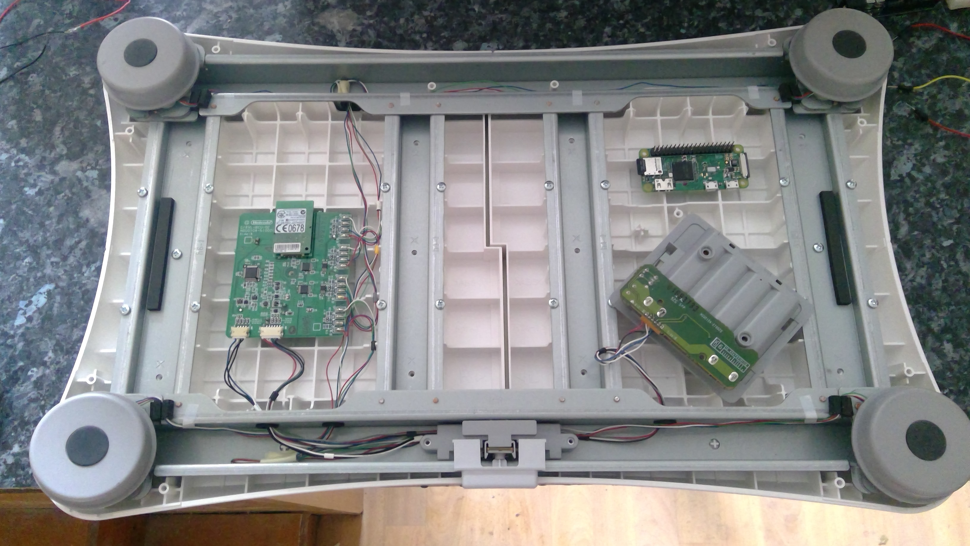
Time to open up the Wii Balance Board and start work on each requirement.
Press the sync button
First, I needed to figure out how the sync button works so I could simulate a press with the electronics. This meant probing to determine if it’s a pull-up or pull-down button, in other words, whether the microcontroller gets triggered when the signal goes high or low.
After some imprecise probing with my multimeter and a couple of wires, I discovered that it uses a pull-up resistor, meaning the microcontroller gets triggered when the pin goes low. This means that my circuit needs to use a transistor to pull that pin low, or connect it to ground.
I’m not an expert, so I needed to do quite a bit of research about how to accomplish this task. I came across lots of technical detail which went over my head. For example, I’m still not sure exactly what situation would require a PNP versus an NPN transistor. However, I settled on using an NPN transistor and a resistor, mainly based on this stackexchange post.
At this point I was happy to solder some wires onto the legs of the button. I used some spare space on my breadboard and connected it according to the diagram. For a quick independent test, I created a voltage divider and provided 3.3V to the base of my BC548.
To my surprise, it worked. I was pretty amazed by this first success, as I wasn’t expecting it to work. Next was to try it using a pin from the Pi, so via a resistor I connected the base to the GPIO pins. The circuit also requires a common ground, so I connected the grounds of the Pi and the board. This test also worked without a hitch. Now onto the next requirement.
Power the board
I checked the Pi power specification and saw that the maximum current draw for the Pi Zero is 1.2A. Moving on to the board, I couldn’t find the current requirements on the labels, so I needed to figure it out myself. I powered the board and used my multimeter to measure the current it draws, and it appears to draw about 50mA. For extra confirmation, I checked the wiki page which states it should last about 60 hours on 4AA batteries. I calculated the expected runtime for 4AA batteries at 50mA, and it comes to approximately 60 hours.
This means that with a 2A USB power supply it could quite comfortably power both the Pi and the board.
Therefore, I soldered wires onto the back of the battery plate and connected them to the 5V and ground rails on the Pi. I powered it on and we had a working balance board. It passed all my tests, so another success.
Buzz the buzzer
This is the simplest of all the requirements, as it only requires connecting one of the pins from the GPIO header on the Pi to the buzzer and the other leg to ground. I tested this with a small python script and it happily buzzed away, which I’m sure my neighbors loved.
All together now
All these electronics are using some spare space on a breadboard and makeshift wiring to the GPIO pins (waiting for connectors in the post). Even so, all the tests of all the electronics worked successfully. The next part is to get it all connected in a more permanent fashion and get the components neatly tucked inside the board.
Bonus: here is a video demonstration: