Wii Balance Board Alarm Clock – Closing the lid
This is the fourth part of this series; the first post is here.
I was nervous, as previous projects have gone wrong at this stage. As things are made permanent, if a problem arises it’s much more difficult to fix, since you can’t easily access the connections to diagnose the issue.
Getting off the breadboard
The first step was to carefully transfer each electrical connection from the breadboard to something more permanent. In this case, I decided to use perfboard. Perfboard is made from the same materials as a PCB but instead of forming circuits it has a grid of pads that you connect yourself.
In my case I had perfboard with horizontal rows of connections. Occasionally, I had to cut through a ridge in the board to break the row. For example, the screw holding the board down would have bridged three rows.
At this stage, I decided to use female connectors on the Pi’s header pins, which allows me to remove the Pi in the future if needed.
I constantly tested my project throughout this process to catch any mistakes early. Fortunately, I managed it without any issues perhaps because it’s such a simple circuit.
Cut and glue
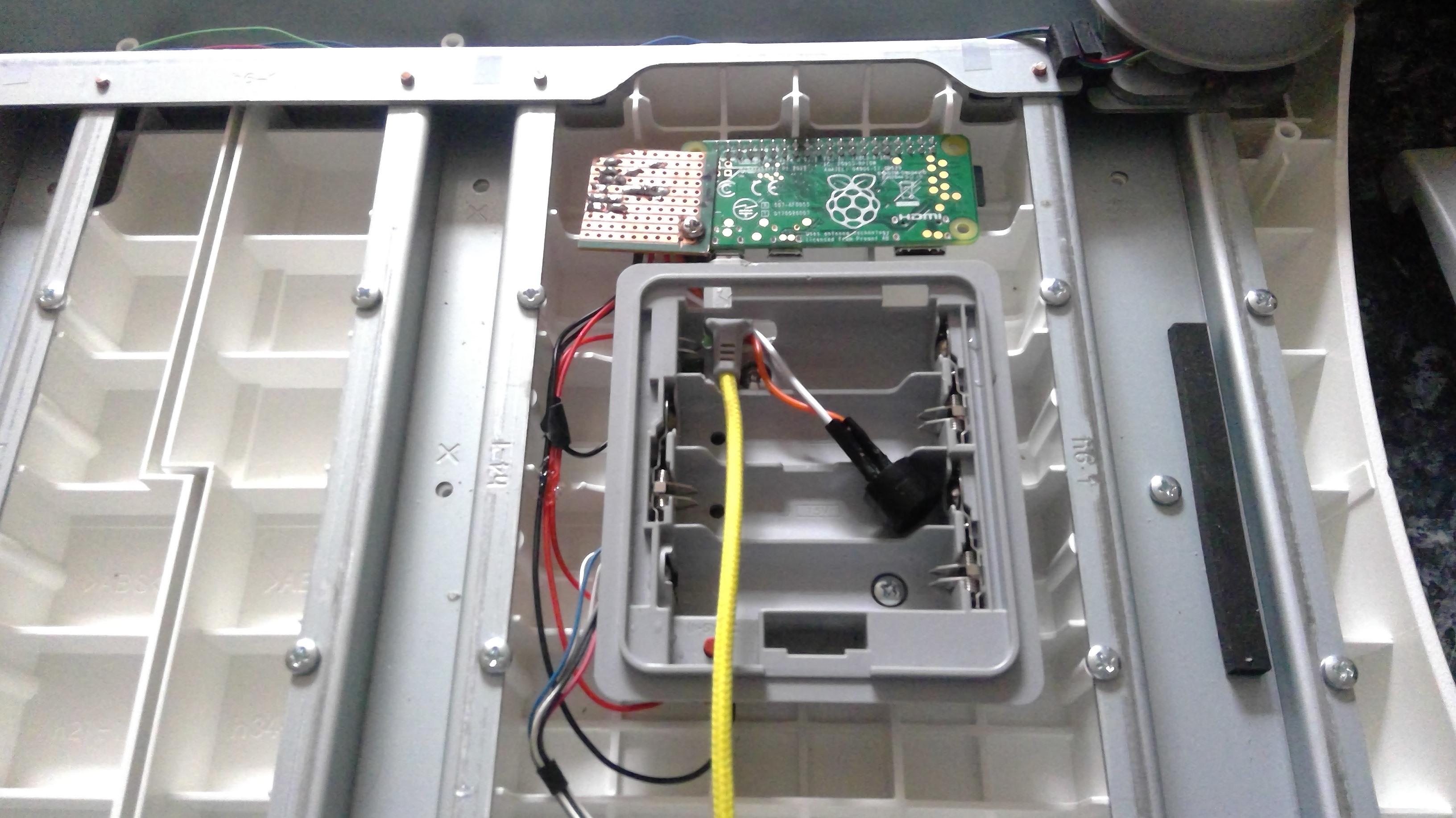
With the circuit completed, I needed to ensure it would fit inside the balance board. The space was just big enough between the reinforcing plastic inside.
The orientation of the Pi meant that a few header pins were separated by the reinforcements. This caused a problem when I connected the Pi to the perfboard, since the separated pins required a connector, preventing them from fitting on either side of the ridge. Therefore, I slightly shifted the Pi across and enlarged the hole in the battery holder to accommodate the USB cable.
Once it looked like everything would fit, I hot-glued a piece of plastic into a corner and secured the perfboard and Raspberry Pi with a screw. It flexes slightly on the other side, but overall, I thought it was good enough, it’s not going to move much.
Closed
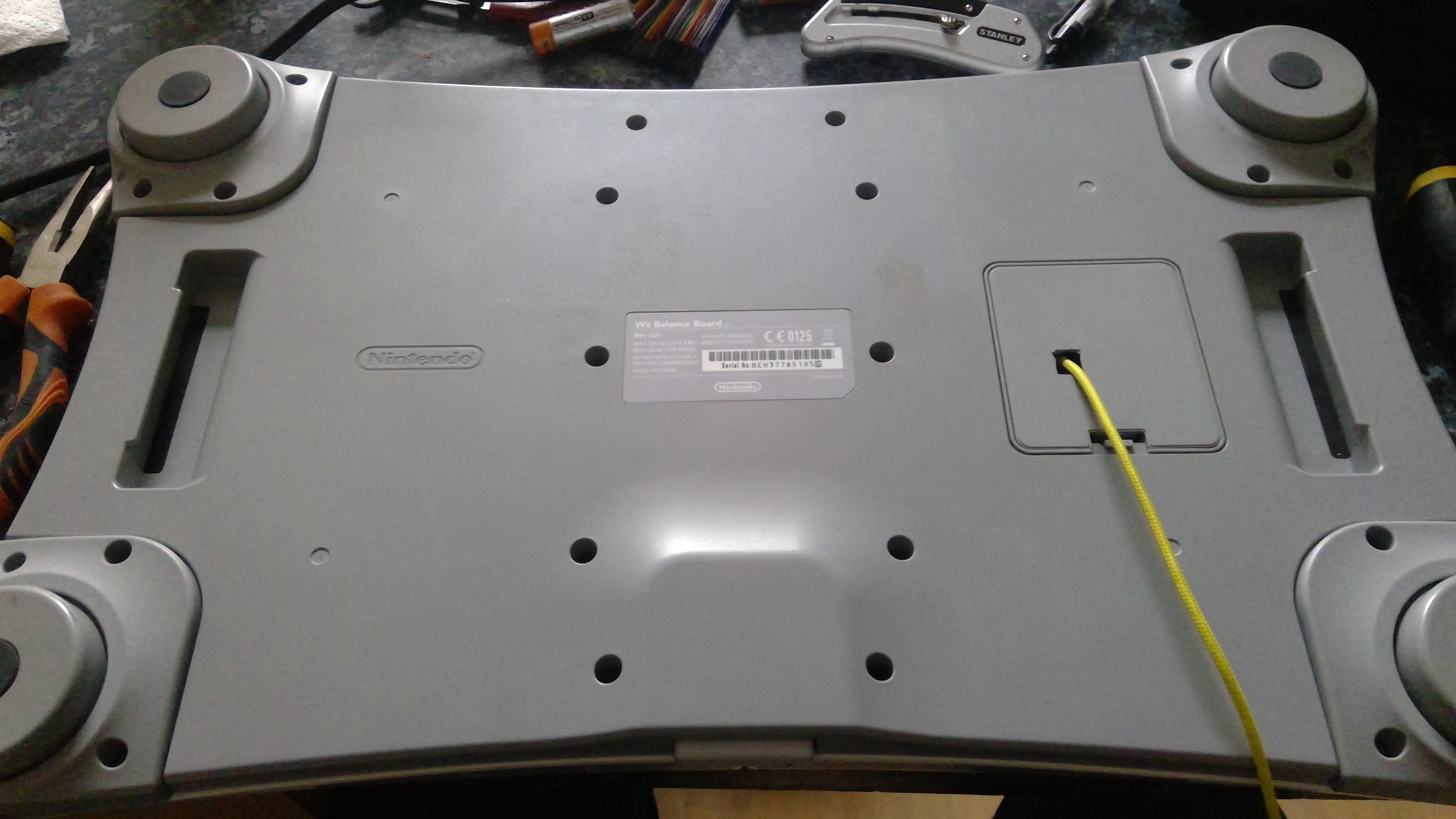
With the electronics in place, I just needed to put the board back together. At this stage, I drilled a hole in the battery cover to pass the USB cable through.
I tested it, and it worked! You can see it in action in the bonus video below.
Now I just need to finish the software, and we’ll have a working alarm.
Bonus: here is a video of the closed board: